
VOLUME 1, NUMBER 2 | SUMMER 1998
"Reverse Engineering" brings sophisticated technology from F-15 cockpit to Beachcraft pilots.
by Tom Inglesby
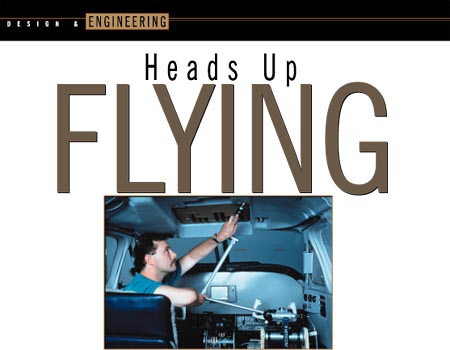
Those who pilot Beachcraft King Airs are in luck. Regardless of the model, they have the same technology available that makes fighter pilots fly easier in tight situations: the heads up display (HUD). In an F-15 � whether in hot pursuit or standoff mode � the HUD allows the pilot to concentrate on the airspace and the instruments at the same time, everything in front and in focus. King Air pilots can have that same capability, without the stress of combat flying, with the installation of the FV-2000 HUD from Flight Visions, Sugar Grove, Ill.
Jim Deppe, a founder and Director of R&D; at Flight Visions, explains, "The obvious benefit of a Heads Up Display is that the pilot spends little time scanning the IP (instrument panel) and more time scanning the airspace. Because our unit is focused at infinity, the pilot's eyes don't have to constantly change focal distance as they switch between the panel's information and the outside during instrument approach and landing. With the FV-2000, the eyes are always focused outside the cabin. That means the pilot can spot traffic quicker because there is no loss of time in refocusing to the environment."
Tests have shown that, when there is nothing on which to focus, human eyes tend to zero in at about 20 to 30 feet in front. The HUD gives the pilot something to see out at infinity, so the eyes are ready to spot trouble quickly.
In the words of Tom Kopacz, chief pilot for De Kalb Genetics (De Kalb, Ill.), "I found it's much easier to spot traffic when flying with the HUD. The [air traffic] controller would call out traffic in the area, and I was surprised how fast I could spot them. [The HUD] would be especially useful on hazy days when visibility is poor. I can easily see traffic or the airport while keeping tabs on altitude and airspeed. The HUD gives you the flight director, airspeed, VSI, altitude, heading, everything you need to make an approach. And it's all displayed �out there,' where you should be looking anyway."
These sentiments were echoed by Mark Pasqualino, chief pilot for Dentsply International. Flying out of the Rockford, Ill., airport, he says, "The HUD diverts your attention outside the cockpit, which is especially good when you're shooting an approach close to minimums (minimum acceptable weather conditions). You're not transitioning your focus (back and forth) from the panel to the windshield."
Cost-effective fit
![]()
Should you be a King Air owner, whether the pilot or not, you'll be happy to note that the FV-2000 won't cost you the arm and a leg you might expect. Perhaps equally important, come resale time, you won't have to make any apologies for the aircraft's cabin appearance since the unit is not only designed to work in the King Air� it is designed to fit in the King Air. Housings and headliners are integrated to give that "factory look" to the installation.
Getting an after-market piece of equipment as sophisticated as the HUD to be configured successfully in a variety of cabins takes more than a sharp designer's pencil; it takes the combined efforts of engineers, designers, mold makers and, in this age, operators of computer-controlled equipment and systems.
Flight Visions uses a computer-aided design (CAD) system from Cadkey (Windsor, Conn.) and a digitizer known as the FaroArm developed by FARO Technologies (Lake Mary, Fla.). Much of the success that Flight Visions has had in adapting the FV-2000 to fit perfectly in multiple cabin configurations comes from the "reverse engineering" capabilities it's developed using the FaroArm.
In the case of Flight Visions, reverse engineering is the technique of measuring the cabin of an aircraft with precision equal to that used by the airframe manufacturer in the original design process. Few aircraft designs remain stagnant for very long. Engineering revisions are made to correct flaws, modify and improve structures, rearrange components for better access or simply to accommodate a particular buyer's preferences. Nowhere is this more evident than in a long-running series such as the King Air. In many cases, interior dimensions and component placement are changed by the airframe manufacturer; often interiors are fabricated by outside contractors that customize the appointments to the buyer's requirements. It is in meeting these many variables that reverse engineering comes in handy.
Walking through
![]()
The FV-2000 is comprised of three elements: the electronics in the avionics bay; the console-mounted control panel used to adjust the brightness of the display and select the navigational information to be displayed; and the optics unit. It is this latter unit that requires the most extensive designing and engineering to fit in multiple environments.
Besides a projector, the unit has an optical quality glass screen, called the Combiner, that is suspended from the headliner-mounted optic unit, placing the screen directly in the sightline of the pilot. When space requirements so dictate, the Combiner can be mounted on the IP. Either way, the pilot looks through the Combiner and then through the windscreen. What is seen is the instrument information "floating in space" in front of the aircraft.
Although Flight Visions manufactures the HUD, they are installed by qualified dealers and FAA licensed service facilities. The installation can be done during overhaul, routine maintenance or inspection. As you can imagine, pilots and owners of commercial and business aircraft hate to have their planes tied up for longer than necessary. Therefore, to speed the process, Flight Visions has taken the necessary dimensions from typical models of the King Air (and other airframes) and created HUDs to fit.
The iterative way
![]()
The first commercial units Flight Visions developed were done the old-fashioned way, by hand, with care and over time. And they were unique in that they were done without tying up an operational aircraft. "Our approach in the beginning was to get a cockpit from a salvaged King Air," explains Deppe. "We went in this shell and took measurements, by hand, of the inside contours and the structure of that aircraft. We then entered that data into the CAD database, again by hand. Our engineers and designers then had to work within the CAD system to find various forms and positions for the optical elements. The problem was to get the Combiner and optical units positioned relative to the pilot's head without being in the way."
What Deppe and mechanical engineer Ron Hunter did was to construct a "manual CAD system." As Hunter recalls, "We set a peg board horizontally across the ceiling and poked thin brass rods through the holes to take measurements. That meant that each point we measured was determined by the quarter-inch spacing of the holes in the peg board. When it came to measuring details, like the location of a rib, we didn't have enough resolution in this system. That led to a long series of iterations to make things fit."
All that took time. "When we found something that we thought would work," Deppe adds, "we'd make a Styrofoam model of the design and take it back to the cockpit and try it. Then we'd revise it to compensate for other problems that we found. It was an iterative process with a lot of manual measurements. If we hadn't had that salvaged cockpit, we'd never have been able to have access to a cabin for the time it took us."
In getting subsequent measurements from other King Air models � and other aircraft � they were concerned about delaying the return of operational aircraft. As Deppe remarks, "The King Air is an expensive aircraft; some of the other planes we are developing for now are much more expensive. It's hard to get a corporate owner to let us have that amount of time with the aircraft." Obviously, to expand the line, Flight Visions needed access to a faster method of determining the true cabin configuration of a variety of aircraft. Enter the technology of today, the FaroArm.
Getting an Arm up
![]()
The FaroArm is an easily moved, articulated arm coordinate measuring machine (CMM) that can input directly to a CAD system. The unit is a six-degree-of-freedom arm with high precision rotary tranducers at each of six joints. These combine to provide complete point positioning and reference coordinates. Formerly called the FARO Metrecom, it is used in medical and industrial applications where extremely accurate measurements must be done on a 3D object, such as the human body.
"Basically, we did with the FaroArm what we were doing with the peg board, only electronically," recalls Hunter. "We set up a grid in the computer, comparable to the peg board �grid' we had in the cabin. But instead of quarter-inch spacing, we can resolve the accuracy down to plus or minus .0005 of an inch."
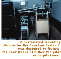
Flight Visions adapted the FaroArm to a quick mount system that puts it into the pilot's seat. Well, not actually into the seat. "It's essential that the FaroArm be rigidly mounted," notes Deppe. "Its accuracy depends on having a base that doesn't move. We built a fixture that clamps the Arm onto the seat track after we remove the pilot's seat." This positioning allows the Arm to be operated in the envelope the pilots operates in. Hooked to a computer, the Arm's movements are converted into digital coordinate measurements for the CADKey database.
Typically, the Arm is mounted in the horizontal position because of the somewhat cramped confines of the cabin. Once the fixturing is completed, and the Arm is considered to be solidly mounted, benchmark or reference coordinates are determined. This operation establishes the base position of the Arm for the database. All following points are referenced to these coordinates.
In the computer database, a grid system is set up so measurements can be oriented in 3D for the development of cross-sections of the cabin. In the case of the King Air, the grid spacing ranges from one-quarter (0.25) to one-eighth (0.125) inch.
The articulated Arm is moved from point to point on the cabin headliner and other structures involved in the mounting of the HUD. The headliner can then be removed and the actual stringers, spars, ribs, weight reduction holes, air ducting, console and instrument locations measured from the baseline coordinates. Each pass enters more data into the system using "sketching" software supplied by FARO. In the end, the engineers have a complete 3D representation of that particular aircraft.
The first aircraft Flight Visions used the FaroArm on was a Cessna Citation business jet. "We set up the Arm," says Deppe, "took measurements of the cabin headliner, all the molded pieces that finish the cabin ceiling, and then we took those parts off and digitized the actual underlying structure of the cabin. That gave us the image of all the plastic and metal parts in our CAD database. We were able to locate all ribs and other structures that could be impacted by the installation of the HUD."
Now what?
![]()
Data collected using the FaroArm creates cross-sections of the cabin in the database and is then used to generate the optimum mounting location for the optical unit. Consideration is given to the ease of mounting the optical unit and modifications needed to either the aircraft or the existing optical unit.
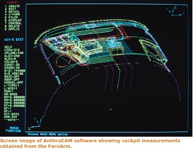
CADKey is then used to develop a wireframe, 3D model of the cabin with the FV-2000 installed. Once the designer is assured that everything will fit, a series of 2D paper drawings of the system are generated for the various suppliers involved.
To make the FV-2000 look as well as it fits, a new headliner is designed to cover the optical unit and blend in with the rest of the cabin. Using the raw data points gained from the FaroArm's digitizing of the actual cabin, a 3D model of the new headliner is generated. This headliner takes into consideration all other components that mount onto or within the structure. The design is then fit checked against the data from the FaroArm, and problems of part interference, such as between the optical unit and the framework beneath the headliner, is checked. If necessary, components of the optical unit can be relocated now, before construction is begun.
The headliner is a thermoform molded unit. Shrinkage is accounted for in the design and full size plots are made for pattern makers. Once the mold is completed, the final part is checked in the aircraft for approval.
Better knowledge, higher comfort
![]()
What are the benefits of using a digitizer instead of the old-fashion methods? "We know we can depend on the CAD model," Deppe is quick to point out. "Once we have that information, it opens up a world of possibilities for us to experiment with new designs and modifications that will produce a better product. Without it, we'd be taking an educated guess about a lot of things, then look for a customer willing to let us tear down the cockpit of their aircraft in order to test the results. This way, we can develop the product before we actually have access to the airplane."
"We can verify a lot of the changes that might be necessary," injects Hunter. "On the King Air project, "we were able to fit check the optical unit into the cockpit on the computer. We could assure ourselves that there would be no interference between the new plastic parts and the original structure. We could see where close tolerances might be a problem for the mold maker and we could warn them."
The result of applying new technology to the design and engineering of Flight Visions HUD is that the company can take on new challenges, new airframes and new applications of their system with the confidence of knowing that the measurements in their design database are accurate and that the company's limited engineering resources won't be stressed beyond their capacity to respond quickly to the demands of the commercial and business aviation marketplace.
Tom Inglesby is the executive editor of Evolving Enterprise.
Web Site © Copyright 2020 by Lionheart Publishing, Inc.
All rights reserved.
Lionheart Publishing, Inc.
2555 Cumberland Parkway, Suite 299, Atlanta, GA 30339 USA
Phone: +44 23 8110 3411 |
E-mail:
Web: www.lionheartpub.com
Web Design by Premier Web Designs
E-mail: [email protected]